


More info
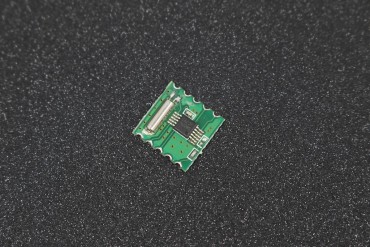
Detail about Display Module
The MAX7219 is an integrated serial input / output common- cathode display driver, it is connected to a microprocessor with 8-digit 7-segment digital LED display can also be connected to the bar graph display or 64 separate LED. On B BCD encoder including an on-chip, multi-channel scanning loop word drive, but also an 8 x 8 static RAM is used to store each data. Only one external register is used to set the current of each LED segment. A convenient four-wire serial interface can connect all general-purpose microprocessor. Each data can be addressed in the update does not need to rewrite all the display. MAX7219 also allows the user to select on each data coding or non-coding. The entire device contains a 150μA low-power shutdown mode, analog and digital brightness control, a scan-limit register allows the user to display the 1-8 bits of data, as well as a let all LED light detection mode. Only need three IO ports can drive a dot-matrix! Dot-matrix display, flicker-free! Supports cascading! This price is the price of the DIY kit, not a finished product prices!
Wiring Instruction
1 - The module left as an input port to the output port on the right.
2 - The control of a single module, simply input port to the CPU
3 - Multiple modules cascade input termination CPU, 2 output termination module, a module of the input of the input terminal, the output terminal of the first two modules of the first three modules, and so on ... 51 MCU, for example:
Specifications
- A single module can drive an 8 * 8 common cathode lattice
- Module Operating voltage: 5V.
- Module size: 5 cm long X 3.2 cm wide X 1.5 cm high
- With four screws hole, aperture 3mm, by using our M3 Tongzhu fixed
- Module with input and output interfaces, supports multiple modules cascade
- Note
- VCC and GND is not reversed, it would burn the chip!
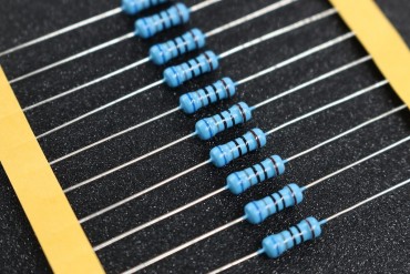
- The P0 port control 51 microcontroller must be connected to the pull-up resistor, it is recommended that the resistance of 4.7K--10K
- Please lattice first inserted into the round hole seat, then inserted into the round hole Block PCB board welding. Lattice word side facing the surface order from left to right pin 123456. PCB board 1 foot square pad!
- Cathode of the electrolytic capacitors long-legged, short legs for the negative; ceramic capacitors without the positive and negative points.
Reviews
No customer reviews for the moment.
30 other products in the same category:
-
RDA5807M...
-
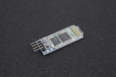
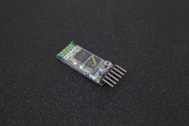
HC06...
-
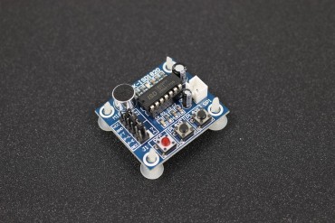
ISD1820...
-

WT588D16P...
-
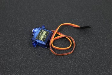
SG90 Tower...
-
Voice...
-

Finger...
-
Ethernet...
-

A4988...
-

BH1750FVI...
-

MMA7660...
-
10DOF...
-

PAM8403...
-
NE555 Pulse...
-
NRF24L01+PA...
-

SI4432 1000...
-

HX711...
-
Rotary...
-

BMP180...
-
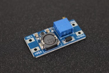
LM2596 ADJ...
-
TTP229...
-

TP4056 1A...
-

MMA7455...
-
HC-05...
-

2.4-GHz...
-
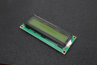
16x2...
-
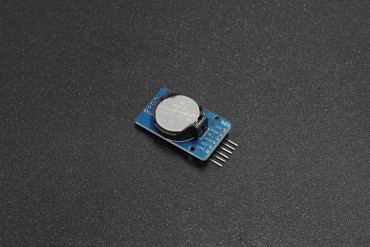
DS3231...
-

IR Flame...
-

MAX 3232...
-

5 Channel...
Customers who bought this product also bought:
-
-
-

-
-
-

-

-
-
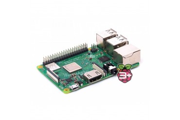
Raspberry Pi...
Remark: Not include free shipping.
-
